I finally got around to taking pictures of some more stages of a Google Fiber install in a new construction neighborhood.
Trenches going into a large vault.
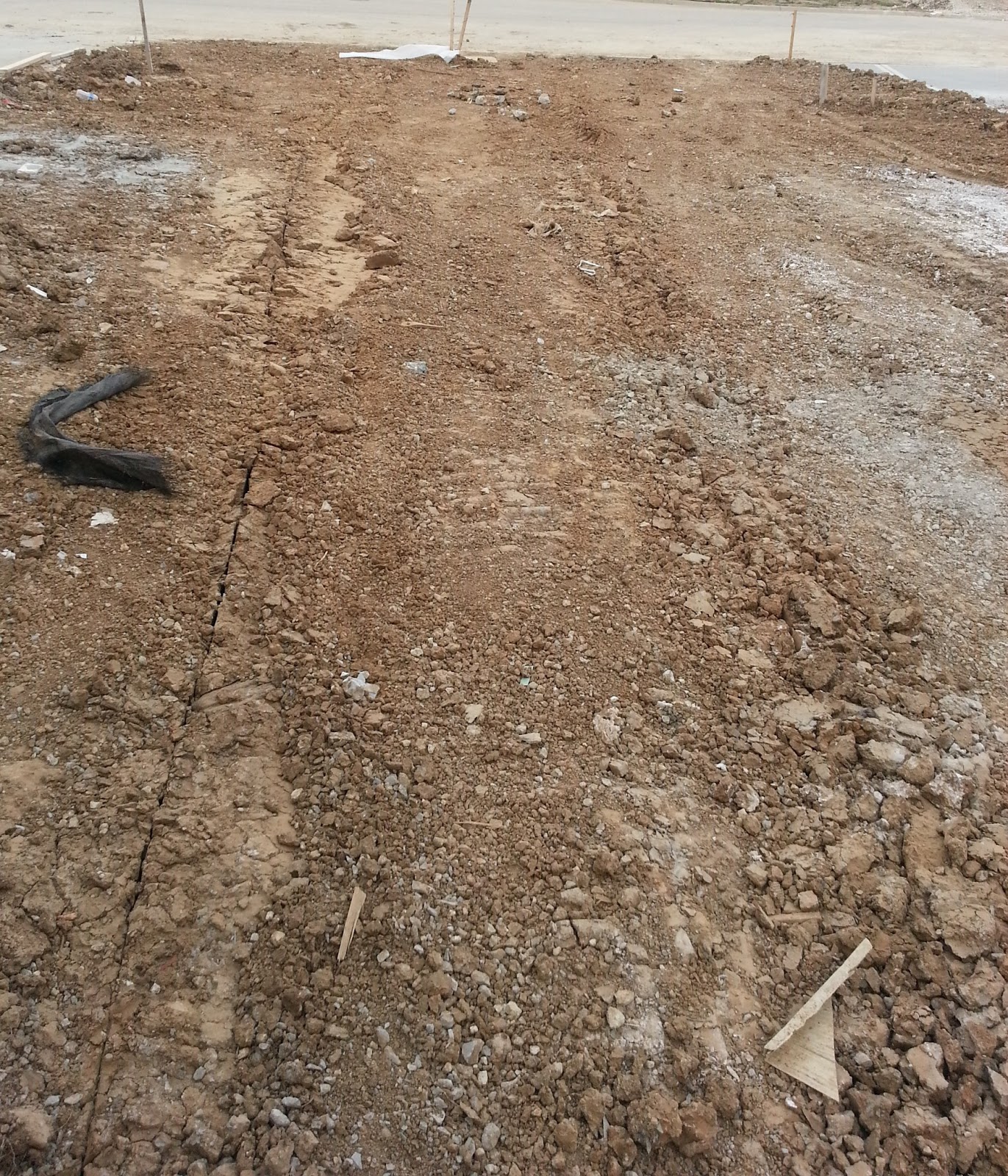
Trenches with fiber in them.

Google Fiber Drop on the side of a house (before installation of the Fiber Jack.) NID - Network Interface Device (Sometimes called the NIU - Network Interface Unit)
Inside of a large vault (With a NAP inside- Network Access Point)
Aerial NAP
Inside of NAP
Inside of a small vault without fiber run through it yet
LCP on the ground- Local Convergence Point in a neighborhood
LCP mounted on a pole


4 comments:
So those of us up north are curious about how our service will be deployed, and from what I've read of your very detailed analysis, from the hut to the home starts on a (probably) 8x multiplexed single strand from the hut to the PON cabinet, then from the PON cabinet to a NAP, and from your picture it looks like individual drop strands leave the NAP to go to the interface box on the house. In one location in Gladstone, they set fairly tiny boxes in-ground on the property line between houses. So would they likely run single strands from the NAP go in conduit to these mini/micro vaults from which they direct-bury drop lines? So if we're on a single strand all the way into the house, they have a circulator built in to the home electronics? Since we're waiting for installations all we have time to do is talk! Just curious what you've seen and if I've followed your description correctly.
NAPs are used whenever splices have to be made. Commonly you'll see them ahead of the fiber into the LCPs and right before the drop lines into homes. You're correctly about the small vaults, they are where the fiber will go from running in conduit to direct burial. They use bi-directional SFPs with splitters/circulator in their circuitry (The Fiber Jack contains the SFP - https://fiber.google.com/img/devices/device-jack.jpg).
From some photos I've seen it looks like they're using cascading splitter design. So Fiber Hut -> 1x4 splitter (Probably inside a NAP) -> (Inside LCP) 1x8 splitter -> Fiber Jack.
Post a Comment